


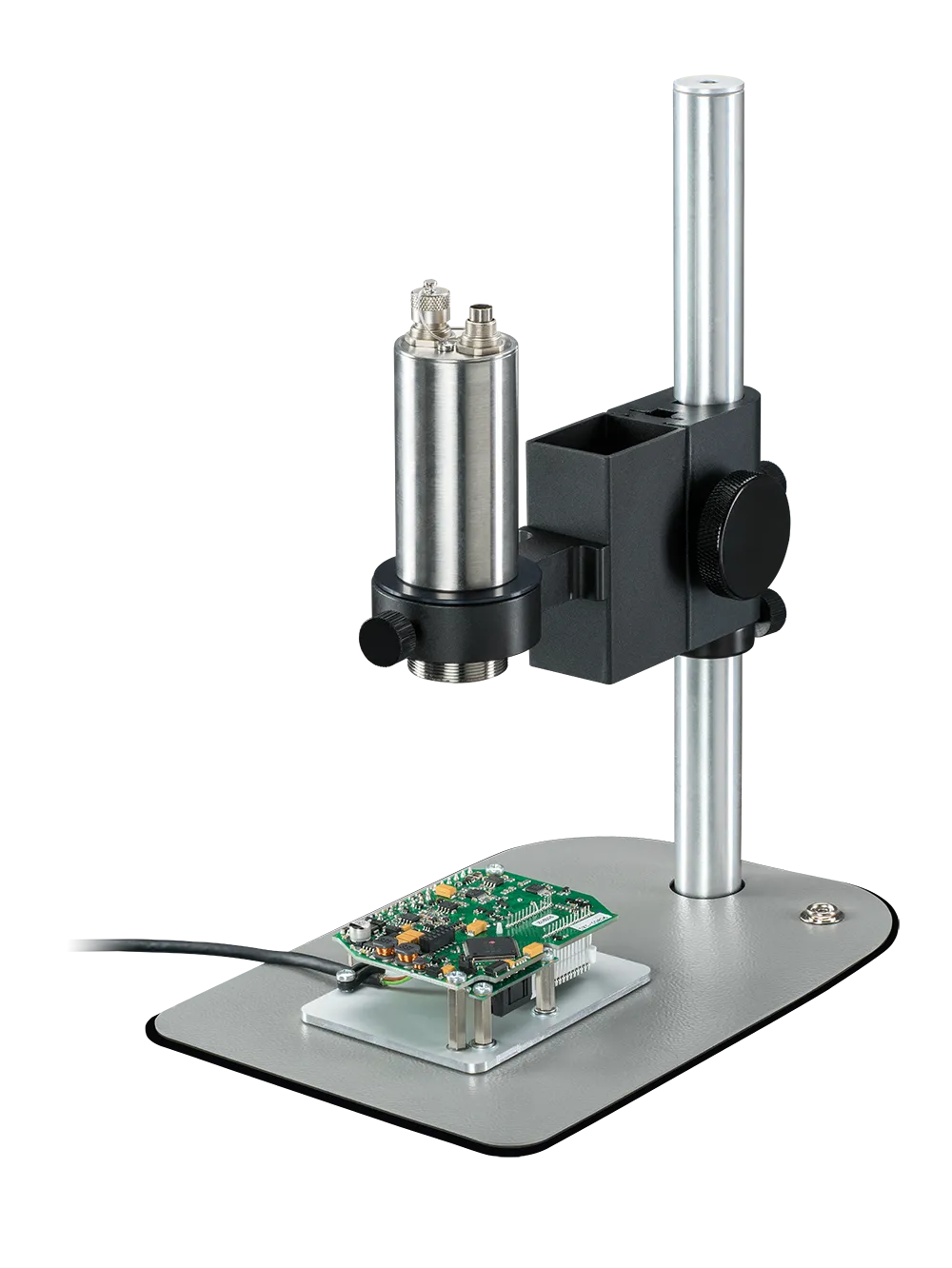
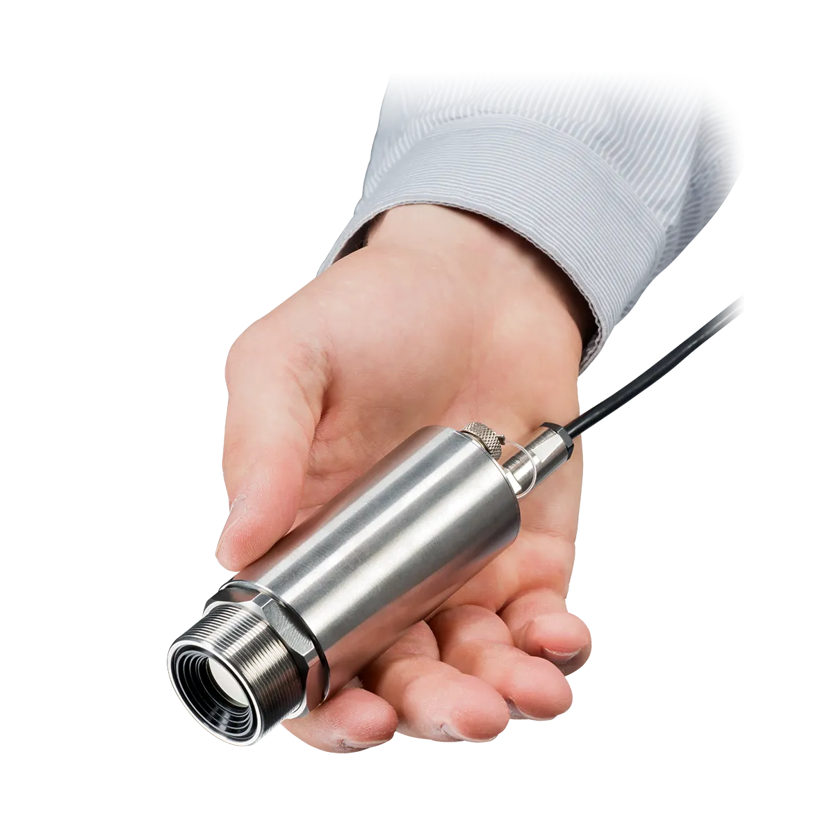
Xi 400 Microscope optics
The microscope optics for the optris Xi 400 infrared camera allow reliable temperature measurement on tiny objects from 240 µm.
- Industrial USB infrared camera
- Small-sized, ruggedized with a motorized focus
- Superb distance-to-spot-size ratio up to 390:1
- Optical resolution: 382 x 288 px
- High frame rate of up to 80 Hz for monitoring fast processes
- Spot size or Instantaneous Field of View (IFOV) is 80 µm
- Accurate temperature measurements of components as small as 240 µm
From $3,095.00
excl. sales taxes, custom tariffs and shipping
Product Description
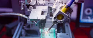
The Xi 400 with microscope optics is the most powerful infrared camera system for printed circuit board analysis and electrical component temperature measurement in the affordable 382 x 288 resolution range. It combines a long-wave infrared camera with a microscope stage for precise focus and German-designed infrared optics optimized for small target images and measurement. This powerful infrared camera package is available in most markets at a budget-friendly price.
Small devices and connections in the electronics industry are common, but most infrared camera systems are built with optics optimized for larger targets. Various specifications are used to describe infrared resolution, making product comparison more difficult. Terms such as Instantaneous Field of View (IFOV), milliradian (mrad), pixel size, detector pitch, and Measurement Field of View (MFOV) are used by different manufacturers to specify this important performance attribute. This variation is partly driven by application requirements, where some cases prioritize temperature increase detection while others require accurate temperature measurement for component specification validation.
To simplify the process of communicating infrared camera resolution, rely on the “IFOV” specification (used interchangeably with spot size or pixel size) to determine a camera’s ability to detect temperature change. Use MFOV to determine a camera’s ability to make an accurate temperature measurement within the IR camera’s accuracy specification. Most manufacturers do not include the MFOV specification, so check with the supplier or multiply the IFOV by a minimum of three to determine a camera’s ability to measure temperature accurately.
The Optris Xi 400 with microscope package is promoted as a superior solution for electronics applications because it was developed with optics designed specifically for this purpose, delivering both a small IFOV (80 µm) and a small MFOV (240 µm). If you are validating small chip operating temperatures and are not aware of this important distinction, you may assume your device is operating within its temperature specification when it is actually running hot and destined to fail early in the product’s lifetime. Accurate remote infrared temperature measurements have great value in many applications, but extracting and analyzing this data from the infrared camera system in other environments can often be challenging.
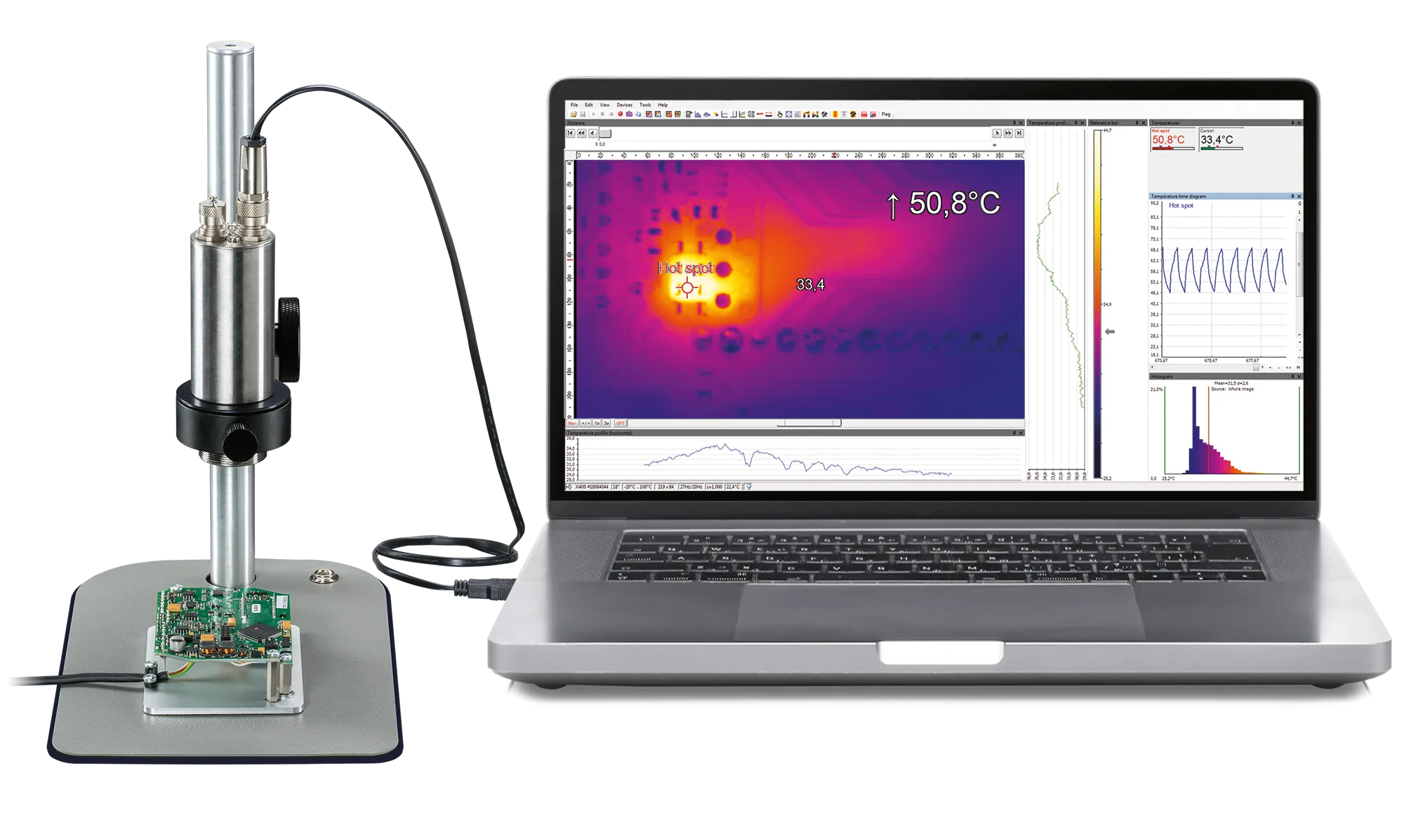
The Optris Xi 400 offers seamless computer connectivity through its primary USB interface and boasts an impressive frame rate of 80 Hz. This high frame rate allows for the monitoring of fast thermal processes, especially in the line-scan mode, ensuring precise and timely thermal data collection for dynamic applications.
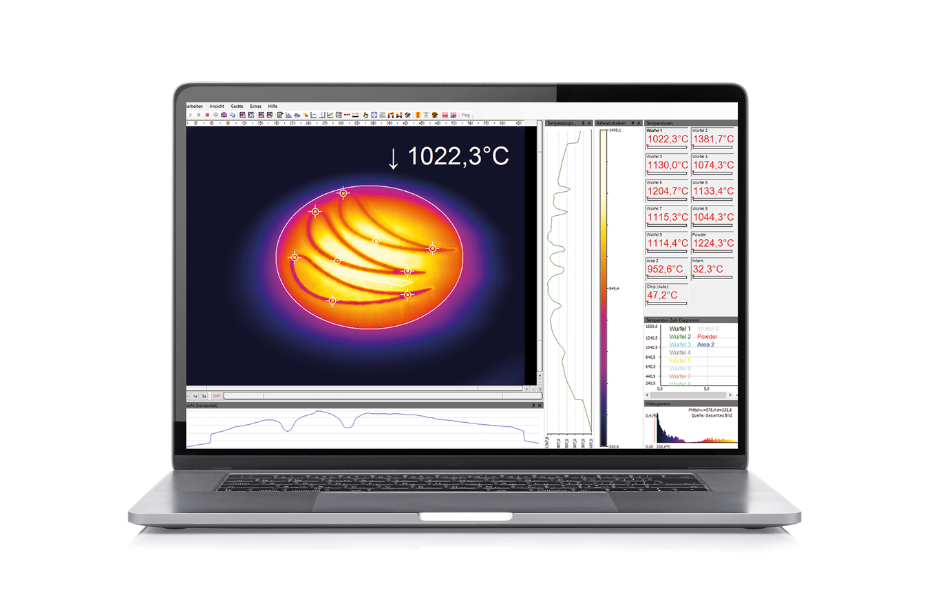
Optris PIX Connect software addresses the challenge of data extraction and analysis by including a Time vs. Temperature measurement feature, which logs data at user-specified intervals and stores it in .csv files. Engineers who prefer full images can use calibrated sequence files or calibrated .tiff images, captured at user-specified intervals. The Snapshot Sequence Storage routine also supports .csv file storage of the complete temperature matrix at user-specified intervals.
With its analog and digital outputs and a process interface, the Xi 400 infrared camera is well-suited for supplying control input to machines and equipment. Software developer kits are available for integrators developing application-specific software solutions. For shorts or fault detection, the software allows engineers to easily optimize temperature display settings to detect even the slightest temperature increases. For more challenging applications, an image subtraction feature is available, enabling users to subtract a live image (such as a fully energized printed circuit board) from the same board with a lower current input, highlighting temperature differences more effectively.
Specification
| MODEL | Xi 400 LT 18°x14° MO |
| DETECTOR | |
| Optical resolution | 382 x 288 pixels |
| Pixel pitch | 17 µm |
| Detector | Uncooled bolometer |
| Spectral Range | LT: 8 µm – 14 µm |
| Optical Filter | No |
| Frame rate | 80 Hz / 27 Hz |
| OPTICAL | |
| Field of View | 18° x 14° |
| Focal length [mm] | 20 |
| F Number | 1 |
| Optical Resolution | 375:1 |
| Minimum Distance to Target | 90 mm – 110 mm (3.54 in – 4.33 in) |
| Interchangeable optics | No |
| MEASUREMENT | |
| Object Measurement Range | –20 °C … 100 °C (-4 °F … 212 °F) 0 °C … 250 °C (32 … 482 °F) (20) 150 °C … 900 °C ((68) 302 °F 1652 °F) |
| Accuracy | ±2 °C or ±2 %, (±3.6 °F or ±2 %), whichever is greater |
| Thermal Sensitivity (NETD) | 80 mK |
| Smallest detectable Spot Size IFOV: 1 pixel | 80 µm |
| Smallest measurable Spot Size MFOV | 240 µm |
| Measurement Field of View (MFOV) | 3 x 3 pixels |
| Warm-up time | 10 min |
| Emissivity /Transmissivity/ Reflectivity | adjustable: 0.100…1.100 |
| INTERFACES | |
| Interface | USB optional: USB GigE (PoE) interface |
| Supported Protocols | USB 2.0 |
| Compatible Software | PIXConnect, ConnectSDK, EasyAPI, DirectSDK |
| ANALOG INPUT/OUTPUT | |
| Direct output/input | 1x analog output (0/4-20 mA) 1x input (analog or digital); optically isolated |
| Optional Industrial Process interface (PIF) | 2x 0 – 10 V input, digital input (max. 24 V), 3x 0/4 – 20 mA outputs, 3x relay (0 – 30 V/ 400 mA), fail-safe relay |
| Cable length | USB: 1 m (3.3 ft) (standard), 3m (9.8 ft), 5 m (16 ft) , 10 m (33 ft), 20 m (66 ft) |
| IMAGE PROCESSING | |
| Configuration | via PIXConnect |
| Operation | Computer-enabled |
| Capabilities | Measure Areas of Interest, Linescanner, EventGrabber, Merger, Alarming, Comparison Functions, Temperature-Time Diagrams, Temperature Profiles, Recording & Playing, Triggering … |
| GENERAL | |
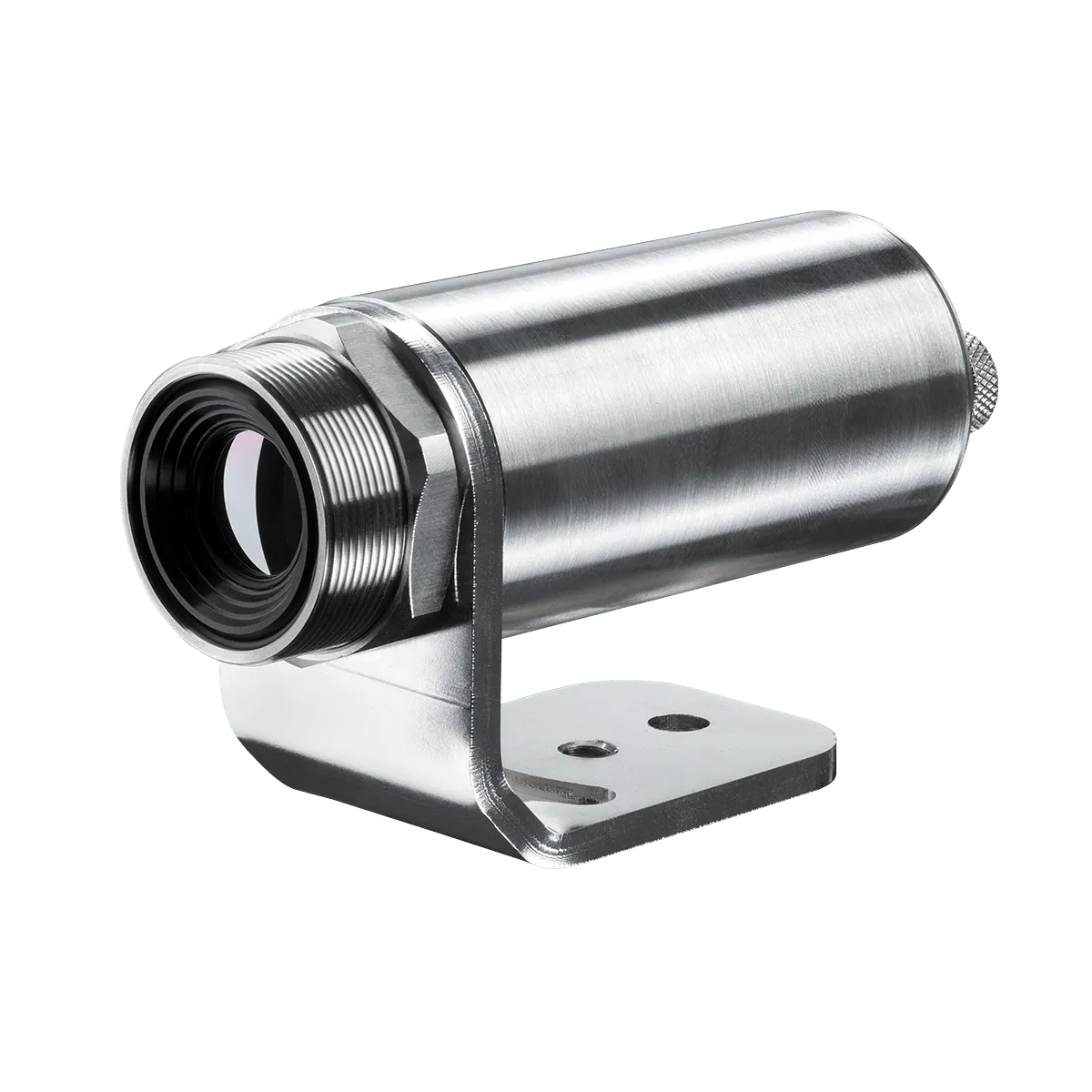
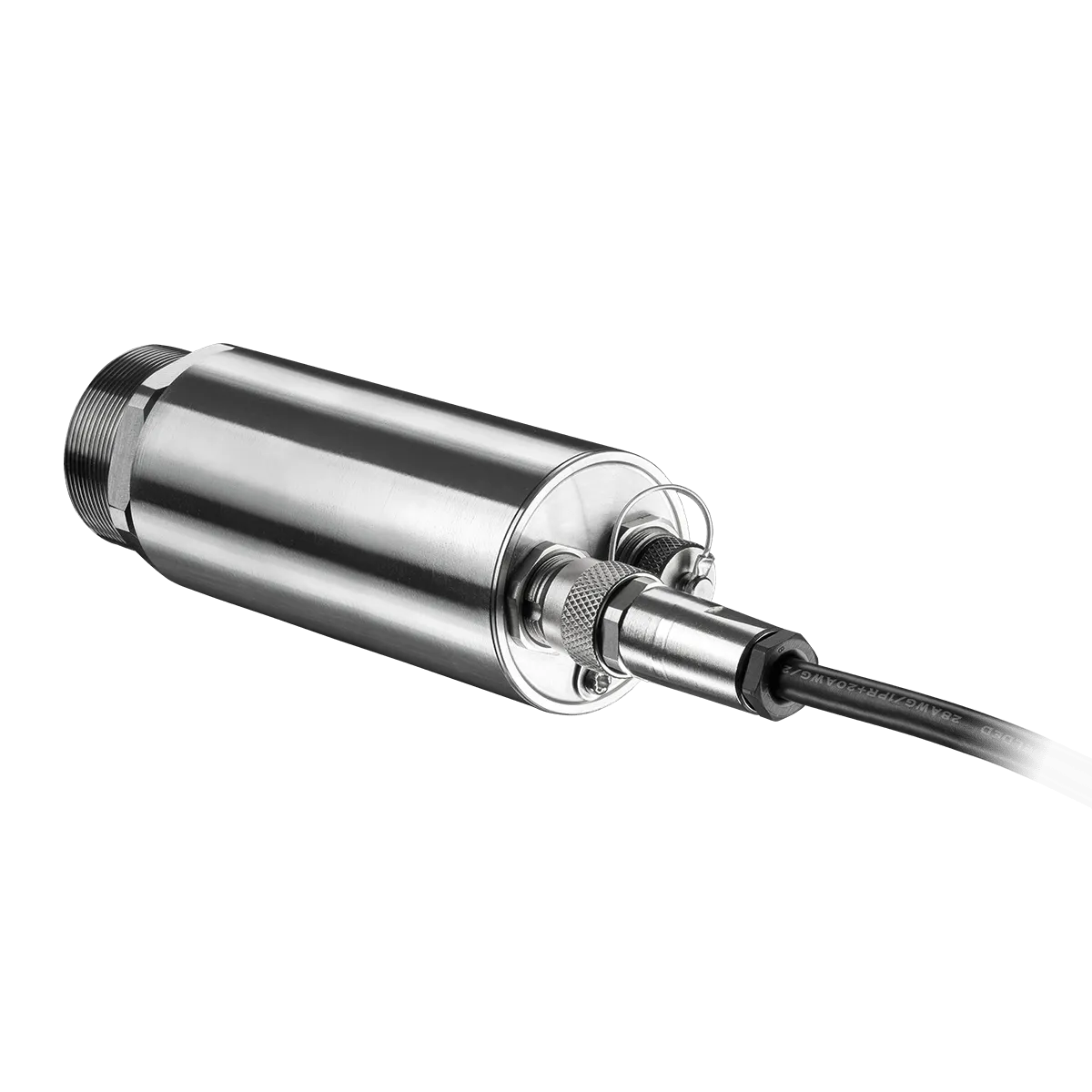
| Size | Ø 36 mm x 100 mm, thread: M30x1 |
| Housing Material | Stainless steel |
| Weight | 216 – 220 g, (7.62 oz – 7.76 oz), depending on lens (without mounting bracket) |
| Tripod | 1/4-20 UNC |
| Focus | Motorized |
| Country of Origin | Germany |
| ENVIRONMENTAL & CERTIFICATIONS | |
| Operating Temperature Range | 0 °C … 50°C (32 °F … 122 °F) |
| Storage Temperature Range | -40 °C … 70 °C (-40 °F … 158 °F) |
| Relative humidity | 10 – 95 %, non-condensing |
| Protection Class | IP67, NEMA-4 |
| EMC | 2014/30/EU |
| Shock | IEC 60068-2-27 (25 G and 50 G) |
| Vibration | IEC 60068-2-6 (sinus shaped) IEC 60068-2-64 (broadband noise) |
| Standards | CE, UKCA, RoHS |
| POWER | |
| Power Supply | USB |
| Power Consumption | max. 2.5 W |
| ACCESSORY | |
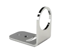
| Microscope stand | Optional |
| ESD pad | Optional |
| Dimensions | 300 x 220 x 150 mm (11.8 x 8.66 x 5.9 in) |
| Part number | OPTXI40LTF20CFT090 |
| Additional Remarks | 1) Accuracy statement effective from 150 °C (302 °F) |
Areas of Application


Software
 Thermography software optris PIX Connect is included and license-free.All infrared cameras are delivered with the thermography software optris PIX Connect, developed specifically for the extensive documentation and analysis of thermal images. The Windows-based PIX Connect software enables users to tailor the infrared cameras to meet specific requirements. It analyses live and recorded temperature data and triggers alarm signals for process integration.The key to leveraging the Optris infrared camera is a correct configuration. This includes detailed device-specific configurations such as frame rate, measurement range adjustments, external communication settings, and USB/Ethernet configurations. Moreover, PIX Connect facilitates firmware updates and the download of configuration files over the Internet.
PIX Connect
Thermography software optris PIX Connect is included and license-free.All infrared cameras are delivered with the thermography software optris PIX Connect, developed specifically for the extensive documentation and analysis of thermal images. The Windows-based PIX Connect software enables users to tailor the infrared cameras to meet specific requirements. It analyses live and recorded temperature data and triggers alarm signals for process integration.The key to leveraging the Optris infrared camera is a correct configuration. This includes detailed device-specific configurations such as frame rate, measurement range adjustments, external communication settings, and USB/Ethernet configurations. Moreover, PIX Connect facilitates firmware updates and the download of configuration files over the Internet.
PIX Connect
 Optris offers several different SDKs for our Xi and PI thermal imaging cameras. Depending on the operating platform, the infrared camera, the coding language, and the hardware platform, different software interfaces can be utilized:
SDK
Optris offers several different SDKs for our Xi and PI thermal imaging cameras. Depending on the operating platform, the infrared camera, the coding language, and the hardware platform, different software interfaces can be utilized:
SDK
 The Optris IRmobile allows users to set up and commission an Optris infrared pyrometer or infrared camera with an Android smartphone or tablet. This tool becomes handy for commissioning and aligning the infrared camera’s field of view or adjusting the configuration. The app analyzes the connected infrared camera’s live infrared image stream with auto hot and cold spot detection. For pyrometers, a temperature-time diagram or the video signal is displayed. This app works on most Android devices running 5.0+ with a USB port supporting USB-OTG (On The Go).
Google Play
The Optris IRmobile allows users to set up and commission an Optris infrared pyrometer or infrared camera with an Android smartphone or tablet. This tool becomes handy for commissioning and aligning the infrared camera’s field of view or adjusting the configuration. The app analyzes the connected infrared camera’s live infrared image stream with auto hot and cold spot detection. For pyrometers, a temperature-time diagram or the video signal is displayed. This app works on most Android devices running 5.0+ with a USB port supporting USB-OTG (On The Go).
Google Play
Downloads
DATASHEET
PDF - 791.49 KB
Xi 400 Datasheet (US)
Complete the form to download the file
FAQs
I like the image clarity on small devices and the ability to accurately measure areas on the board that are smaller than 250 µm, my PCB is much larger than 30mm (1.18 in), and I would like an optic option that delivers both a small spot size and a wide field of view. Can you supply this?
Optris does make a camera package (Pi 640i microscope package link) that includes a high-resolution IR camera that can be mated with a wide field of view optics or microscope optics. The user can switch the optics, and PIX Connect software supports calibration files for both optics. The Xi 400 is built with fixed optics that cannot be changed in the field. Some customers buy two Xi 400 cameras with different optics to support microscopic measurements and full printed circuit board thermal analysis.
Why is the MFOV (Measurement Field of View) specification hard to find on most infrared camera websites?
Some manufacturers are unaware of how single-pixel measurements impact the accuracy of the measurements produced with their cameras. The distinction between MFOV and IFOV can be difficult to communicate. Referencing the MFOV specification instead of the smaller IFOV specification may convince some customers to choose the thermal imager they perceive as the instrument with a smaller IFOV. Also, an engineering effort associated with determining MFOV is time-consuming and often varies with different IR camera products. Finally, some high-resolution infrared cameras use detectors with very small elements (small pitch) which often require more pixel coverage in order to fully respond to emitted temperatures. Some IR cameras will have an MFOV specification 7 times the size of the IFOV. Disclosing this specification will highlight a product deficiency if the application requires accurate temperature measurement. Both the MFOV and the IFOV for all Optris cameras are provided on the Optris Calculator.
Why does it matter if I use the IFOV to determine the size of components I can accurately measure?
Because your temperature measurement will always be lower than the true component temperature. Lower temperature pixels around the single pixel on the hot component will influence the measurement, decreasing the reported temperature. Electric components that run hotter than specified will have a lower lifetime than specified for the component. As a rule of thumb, the operational lifetime of an electric component can be reduced by ½ for every 10 °C (50 °F) the component operates over temperature.
Is the camera frame rate important?
It depends. Some applications, such as finding a fault or shorts on an energized board with constant current input, do not require fast measurements, and a camera with a 9 Hz frame rate will be adequate if equipped with adequate optics. Pulsing circuits and other electronic applications involve transient data collection and understanding the temperature dynamics at intervals of 80 Hz can yield valuable information about device performance.
Many materials on my PCB have varying emissivity. Can I collect temperature data of any value with a thermal camera?
Yes, you can. Most integrated circuits are made with silicon (low emissivity) but are packaged in ECN or other variants of thermo-plastic, which have very high emissivity. They are excellent targets for remote infrared temperature measurement, as are common electrical components such as resistors and capacitors also coated with thermos-plastics. Ceramic packaging is also a very good emitter (roughly .85) and can yield excellent temperature data when proper emissivity is entered into the software. Metal leads or conductor paths, Kovar, or other metals used for integrated circuit packaging will not yield accurate temperature data when measured with long-wave infrared cameras unless they are coated or painted to improve emissivity.
Can I switch between MO2X and MO44 optics?
Yes. Optics can be changed in the field and deliver calibrated temperature measurements, provided both optics are calibrated with the specific PI 640i they are mated with. For correct calibration, make sure to select the optic attached to the camera from the pull-down optics box in the Device tab of the Configuration menu. All optics that have been calibrated with your serial number camera will be visible in this box if the PC hosting PIX Connect software is online.
Can I use non-microscopic field-of-view optics for larger targets such as printed circuit boards?
Yes. Four additional optics are available for the PI 640i and can be calibrated for use with the camera. This dramatically extends the PI 640i’s application potential, enabling thermal imaging and temperature measurement of full-size printed circuit boards or the products that host them. As with microscope optics, make sure to select the correct calibration file when switching optics.
I have my microscope optics. Can I use these?
Microscope optics developed with visible light cameras will not transmit infrared radiation emitted in the spectral region where the PI 640i is responsive and cannot be used with an infrared camera. Infrared optics not calibrated with the PI 640i could potentially deliver magnified thermal images but will not deliver calibrated temperature measurements.
Why do I need a microscope stage?
Macro focus can be performed using the knurled ring on the outside of the microscope objective but minute adjustments in working distance can dramatically improve image clarity and temperature measurement accuracy. Each microscope package’s stages facilitate this minute working distance adjustment. If the image is not in optimal focus, the temperature measurements will not be accurate.
Can I measure the temperature of the leads connected to my small electronic devices?
Small leads can be seen with powerful infrared microscope optics but are most often made of low-emissivity metals that reflect heat energy. Leads need to be coated with carbon black or flat black paint to be accurately measured with an infrared camera. The same is true for a component (can) made from metal. If a metal lead cannot be treated with a high emissivity coating, the high emissivity connection point of the lead to a device can often serve as an indication that the lead in question is running hotter than desired.
Can I see through the layers on a printed circuit board?
FR-4 and Teflon (PTFE) are common materials used as substrate layers in printing circuit boards. They are not transmissive in the infrared region so you cannot see through them with an IR camera. However, heat from a specific region may conduct up through the various printed circuit board layers to the top board, presenting any conducted heat to an infrared camera targeted at that region on the board surface. The camera settings may need to be optimized to enhance sensitivity so that small shorts from inner layers can be seen. Copper foil inserted in between PCB layers can mute or entirely prevent the flow of heat from the inner layers to the top surface of the board.
Can an infrared camera validate chip and substrate temperatures during PCB manufacturing?
Any infrared measurement requires a clear line of sight between the camera optics and the surface to be measured. Infrared temperature measurements in a reflow oven would be impossible without an access port and mounting and camera cooling provisions. Although there is no system actively marketed now with this capability there is one forced-convection SMT reflow system in development using Optris IR cameras in line scan mode to measure temperatures and create full infrared images through small slits in the oven in four locations.
Scope of Supply
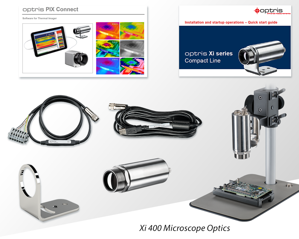
- Process imager Xi 400
- USB cable (1 m / 3.28 ft)
- Cable for output/input (1 m / 3.28 ft) incl. terminal block
- Mounting bracket with nut
- Software package optris PIX Connect
- Quick Start Guide
Related Products


Talk to us about your IR Temperature Measurement Requirements
Our Infrared Temperature Measurement experts can help you find the right Optris product for your application.
