

Calibration
Calibration involves determining the relationship between the display value of the infrared thermometers being tested and the indication of a calibration standard at specific temperatures, along with associated uncertainties. In the past, this process wasn’t clearly distinct from determining regulations for correcting indicated values or creating calibration curves.
There are no general specifications or recommendations for required calibration intervals; these depend on usage, ambient conditions, user requirements, and should be defined as part of quality management for test equipment. Harsher environmental conditions may necessitate more frequent testing of the device. Sustained high ambient temperatures can affect detector sensitivity, while dust and vapors can impact optic transmissivity.
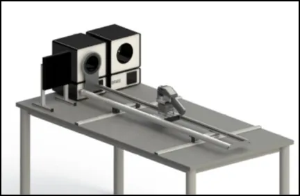
Infrared thermometers are calibrated using calibration radiators, which generate radiation of known temperatures for adjustment and calibration. To achieve low calibration uncertainty, the radiation temperature generated by the calibration radiator must be known as precisely as possible. One way to determine the radiation temperature of a calibration source is to measure its temperature with a contact thermometer and determine its emissivity. Another method is to measure the radiation temperature directly with a transfer standard radiation thermometer (TSRT).
National metrology institutes have high-precision blackbody radiators whose radiation temperature is traceable to the international temperature scale of 1990 (ITS-90) with small uncertainties. These are used to calibrate transfer standard radiation thermometers (TSRT), which can then be used to calibrate a calibration source in the calibration laboratory, which is then used directly to calibrate the infrared camera or pyrometer to be tested.
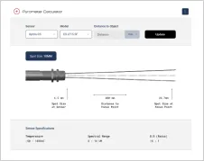
As measurement geometry can influence readings due to the “size-of-source effect,” calibration is generally conducted for a specifically defined geometry (distance and aperture diameter of the radiation source). This information should not be confused with optical resolution values (the distance-to-spot size ratio). The D:S indicates at what object size the signal has dropped to 90% of the original value relative to the calibration geometry. The 100% value applies to the calibration geometry, which always prescribes a larger measuring spot diameter at a certain distance than would be obtained from the D:S.
Favorable measurement conditions must be created regarding the environment. The temperature and humidity in the laboratory room should correspond as closely as possible to the calibration ambient temperature and humidity specified by the manufacturer (usually 23 °C ± 5 °C and 50% (RH) ± 30% (RH)). Changes in ambient temperature must be below 0.1K/min, as many measuring devices and emitters react sensitively to this. Additionally, radiation sources, especially panel radiators, are sensitive to air currents, which should be avoided.
Equipment with a surface temperature differing from the ambient temperature in the laboratory should be arranged to prevent reflections from hot or cold surfaces on the calibration black body and apertures, as well as direct interference radiation in the field of view of the infrared camera. Influences such as electromagnetic fields or mechanical vibrations and shocks should be considerably below the values specified by the manufacturer.
For more details on the calibration of infrared imagers, refer to “Technical temperature measurement – Temperature measurement with thermographic cameras – Metrological characterization – Corrigendum concerning standard VDI 5585 Part 1:2018-03.” For details on the calibration of pyrometers, refer to “Temperature measurement in industry – Radiation thermometry – Calibration of radiation thermometers VDI 3511 Part 4.4:2005-07.”
Back to Lexicon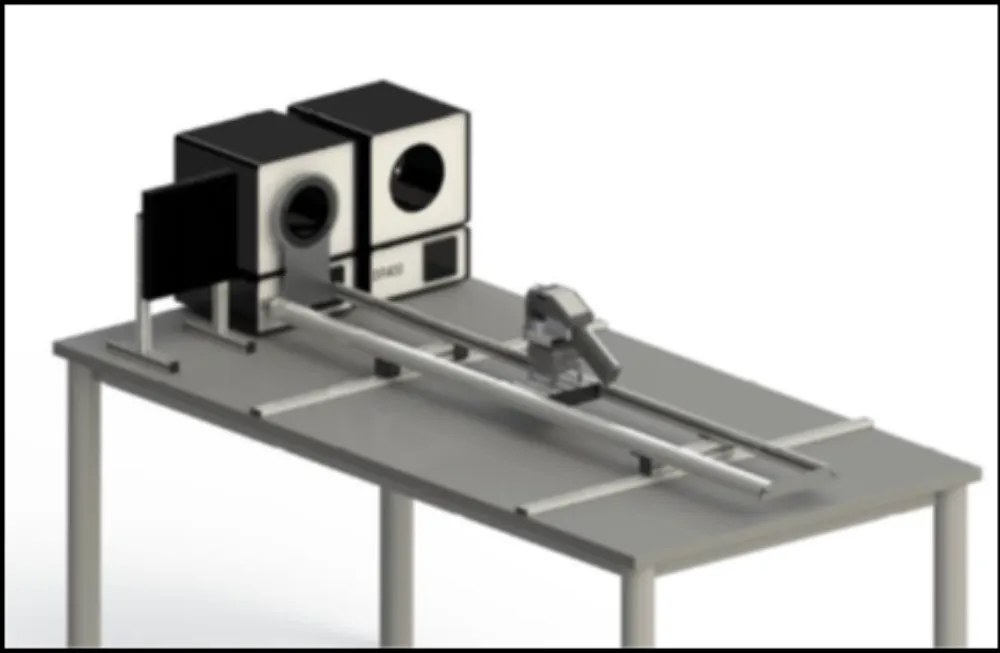

Talk to us about your IR Temperature Measurement Requirements
Our Infrared Temperature Measurement experts can help you find the right Optris product for your application.
