

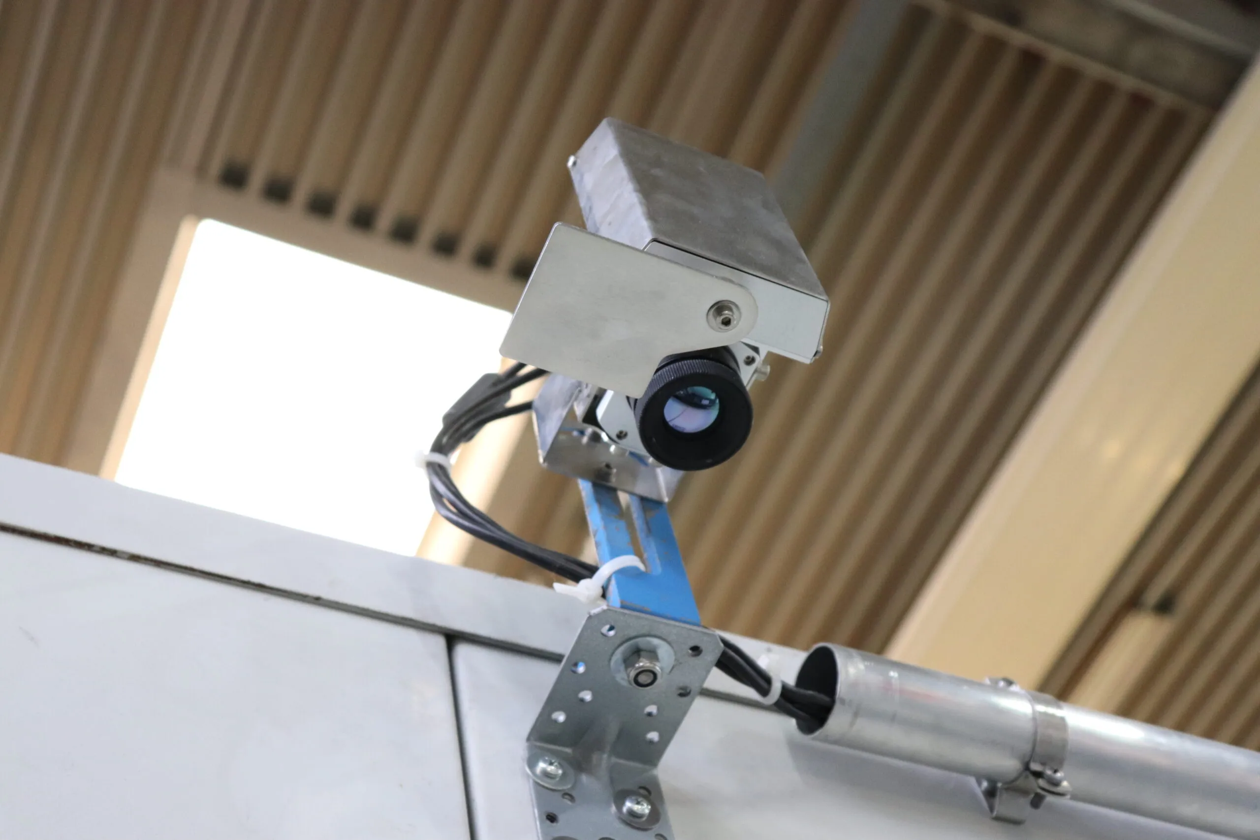
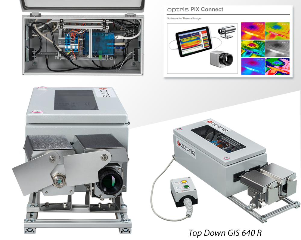
Top-Down Glass Inspection System 640 R
The Top-Down Glass Inspection System quickly detects temperature differences during glass hardening processes, preventing rejects and providing automatic quality monitoring.
- Top-down system with additional reference pyrometer from below for automatic emissivity correction
- Digitally controlled lens protection system (DCLP) avoids extra air purging
- Glass area calculation
- Pre-assembled system for easy installation on glass tempering furnaces
- Automatic scan line adjustment – insensitive to distortions
10.150,00€
Product Description
Low-emissivity (Low-E) glass, designed to enhance energy efficiency in buildings, presents significant challenges for traditional infrared (IR) devices, which measure glass temperature from above as the panes exit the furnace. Commonly used for windows and facade components, Low-E glass is typically constructed as multi-pane insulating glass with a very low emissivity coating. This low emissivity complicates accurate glass temperature measurement by traditional infrared line scanner devices, as they generally target the coated side from above, leading to potential inaccuracies in temperature readings and quality control issues.
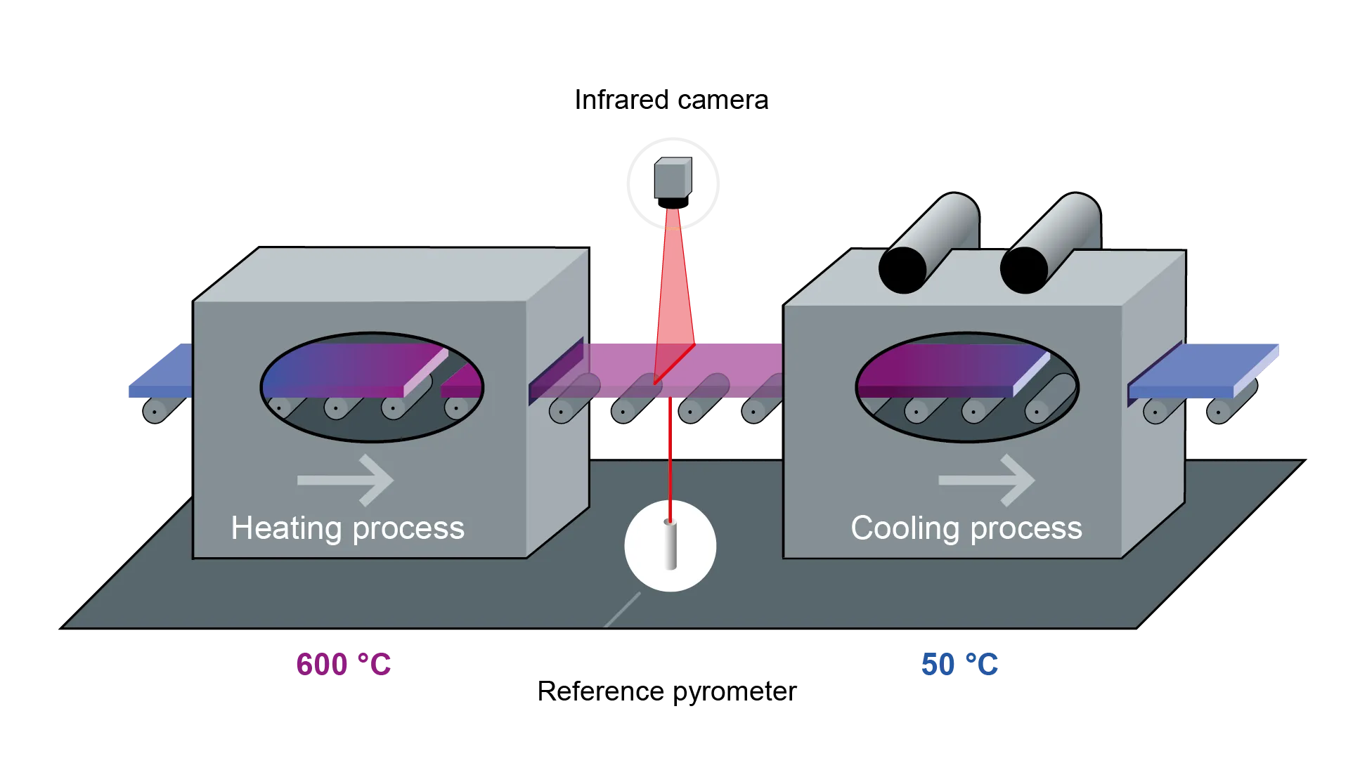
The Top-Down Glass Inspection System (Top-Down GIS) has been developed to address this issue. This system aims to provide accurate temperature measurements of Low-E glass during production. Unlike the Bottom-Up GIS, which measures from beneath the glass, the Top-Down GIS measures from above while using an additional reference pyrometer from below to correct for emissivity. This dual measurement approach ensures that defective or inhomogeneous surfaces can be detected and allows for adjustments in heating or cooling based on the temperature distribution, ensuring optimal quality and consistency in glass production.
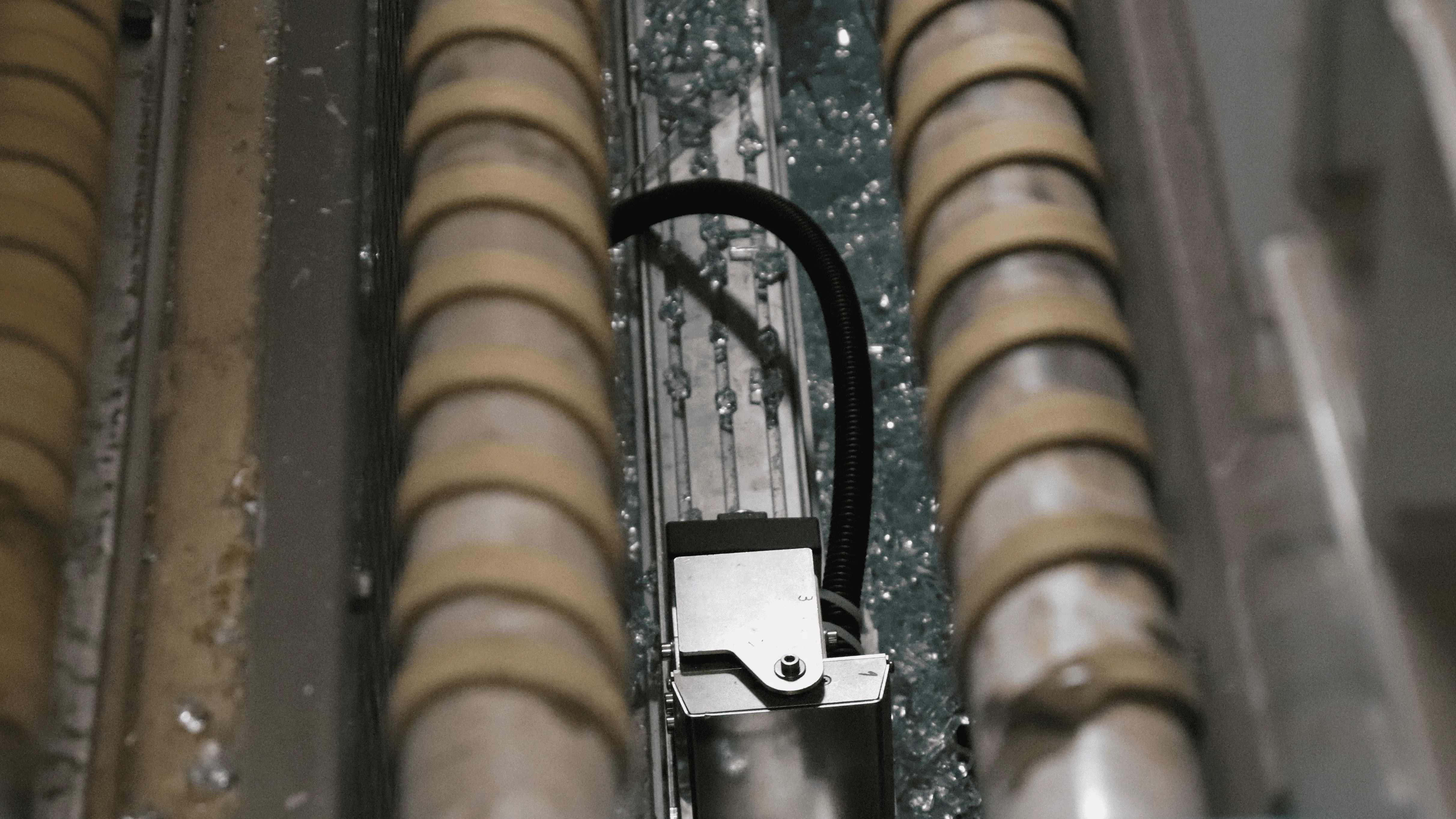
Referencing from below is necessary for two reasons: the coated upper side of the glass has low emissivity, making accurate measurement difficult, and there is often insufficient space for cameras to measure from below due to the low furnace height. This setup would require more than one camera, and a wide-angle view could influence measurements differently. By using an additional reference pyrometer from below, the Top-Down GIS can correct for emissivity variations and ensure accurate temperature readings, even in the confined space of a furnace. This dual-camera approach enhances the system’s ability to detect defects and maintain precise control over the glass production process.
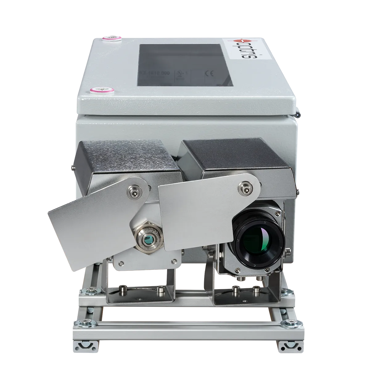
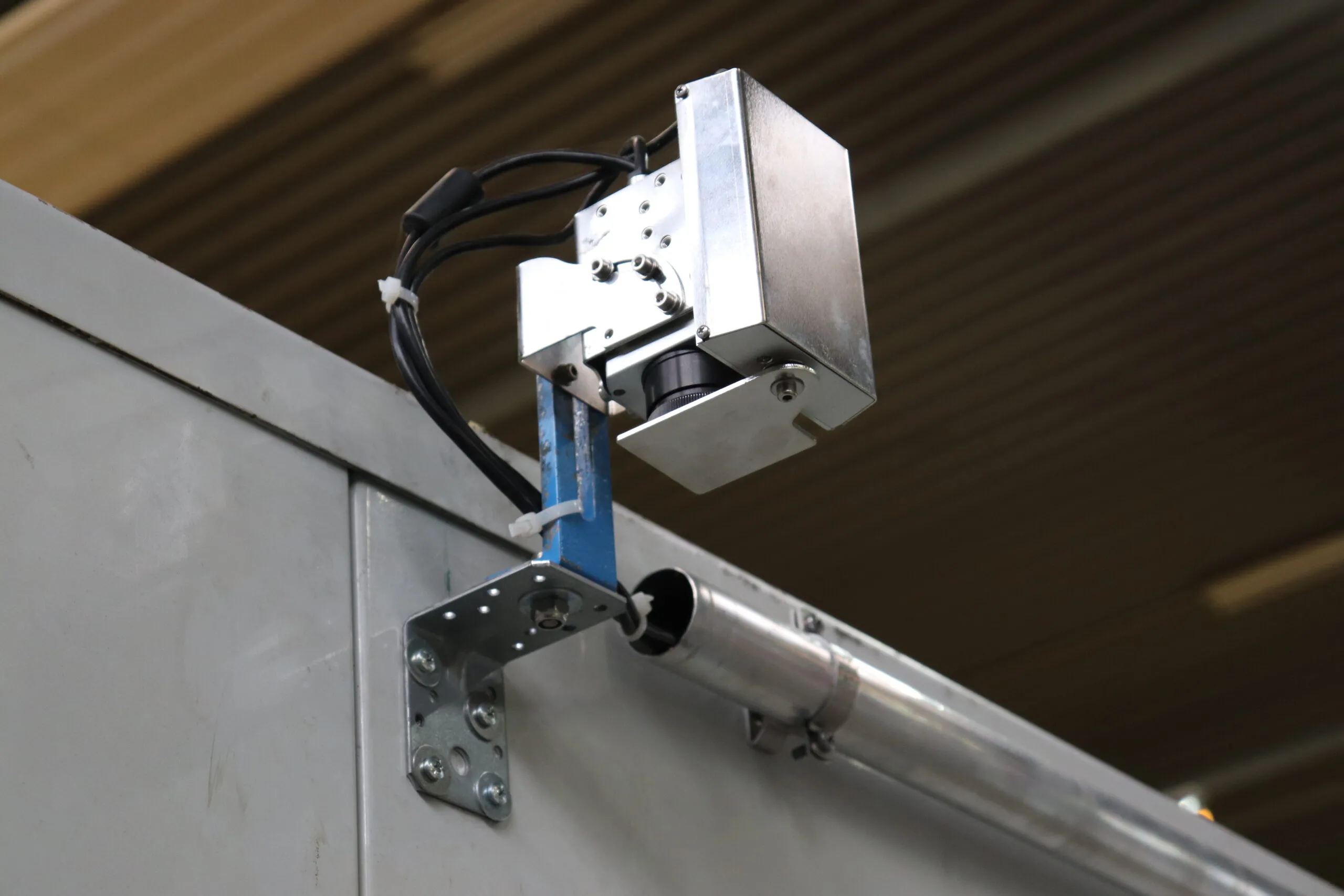
The Top-Down GIS employs two high-resolution infrared cameras positioned above the tempering line to measure the temperature of the top side of the glass. This system, particularly the Top-Down GIS 640 R, includes temperature referencing from a sensor below and automatic emissivity correction for both standard and Low-E glasses. It was specially developed for process control in glass tempering machines. The linescan function with the PI camera from above, combined with reference measurements from the pyrometer below, is essential because Low-E coatings minimize IR radiation through the glass but not the thermal effect of visible light. This dual-measurement approach ensures accurate temperature readings and effective process control, maintaining the quality and consistency of the glass production.
The infrared cameras used in the Top-Down GIS, such as the integrated PI 640i G7, have been specifically developed for the glass industry. These cameras have a spectral response of 7.9 μm and a temperature range of 150 °C to 1500 °C, making them suitable for a wide range of applications in glass production, refining, and further processing. Combining these cameras with the advanced reference pyrometer ensures accurate and reliable temperature measurements across various glass products, including glass panes. The high resolution enables precise temperature mapping and comprehensive coverage of the entire glass surface, ensuring no area is left unchecked.
The system includes a digitally controlled lens protection system (DCLP), which eliminates the need for extra air purging. This glass inspection system allows temperature differences during glass hardening processes to be quickly detected, thus avoiding rejects and providing automatic quality monitoring. The DCLP ensures that the lenses remain clean and operational, enhancing the overall reliability and efficiency of the system in maintaining high-quality glass production standards.
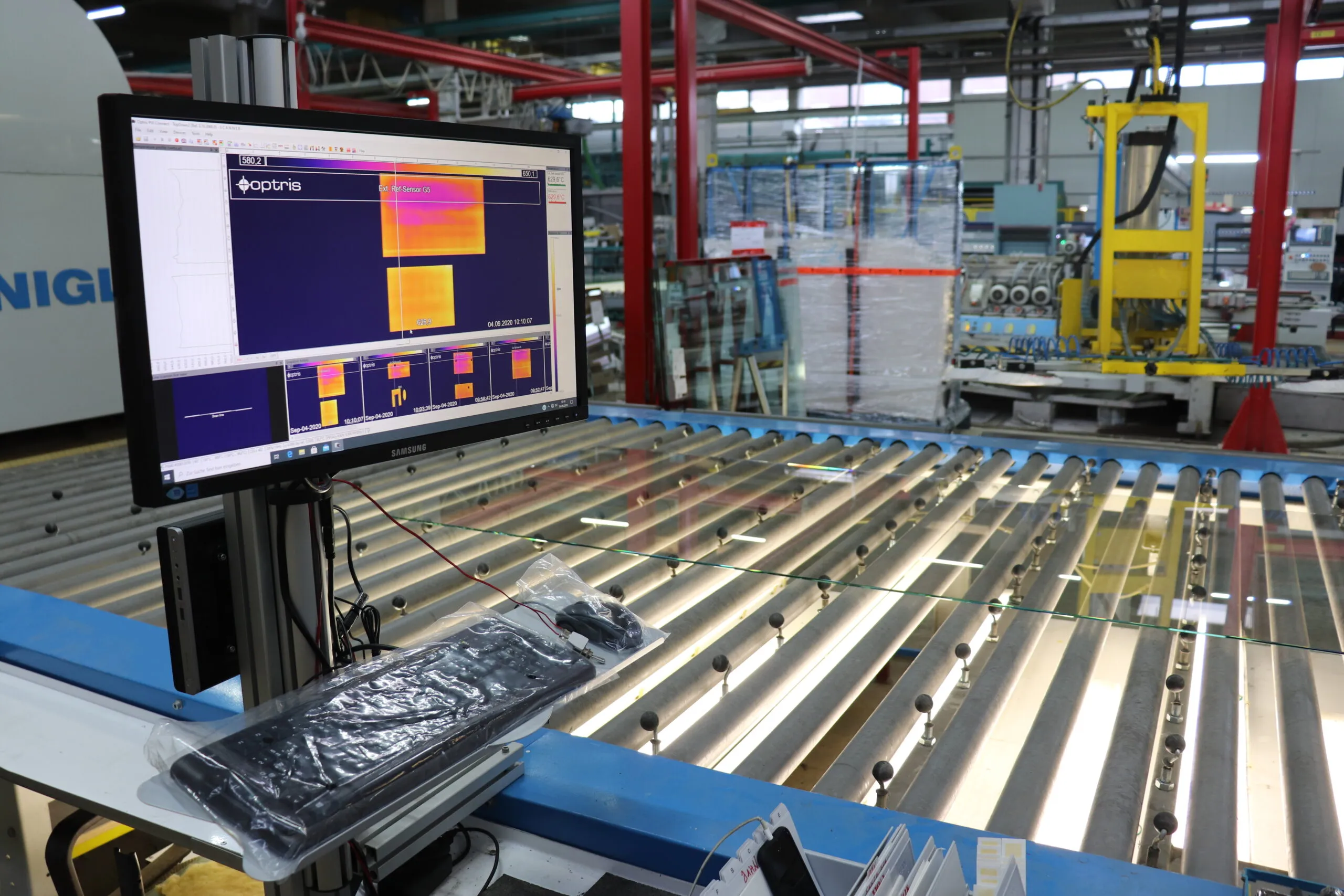
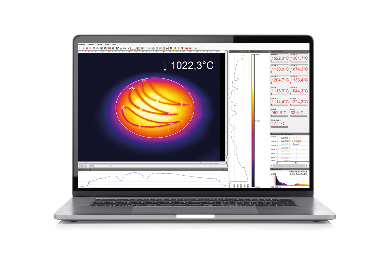
Optris infrared cameras come with license-free PIX Connect software, enabling the cameras to operate as line scan cameras. Traditional line scanners, used in the glass industry for various measurement procedures, are bulky, expensive, and require significant manual effort for setup. In contrast, the infrared camera system is compact and cost-effective, offering several benefits. The software allows for flexible positioning and dimensioning of the scan line, providing complete IR images for valuable additional information, especially during setup. This flexibility simplifies the installation process and enhances the overall efficiency and accuracy of temperature measurements in glass production.
The cameras can accurately measure the surface temperatures of moving objects using minimal apertures, a function particularly significant in the glass industry. Since the glass temperature directly impacts its quality, accurate temperature measurement at multiple points during production is crucial. The data collected is transmitted directly to the process control system, enabling real-time adjustments and ensuring optimal product quality. This capability helps maintain consistency, reduces the risk of defects, and enhances the overall efficiency of the production process.
In addition to measuring temperature distribution, the Top-Down GIS calculates the glass surface area. This capability is essential for process control and quality assurance, allowing for a detailed analysis of the glass during production. The system’s ability to provide accurate temperature data helps maintain the quality and consistency of the glass, which is critical for its performance in energy-efficient applications. By ensuring precise temperature monitoring and surface area calculation, the Top-Down GIS supports the production of high-quality glass products that meet stringent industry standards.
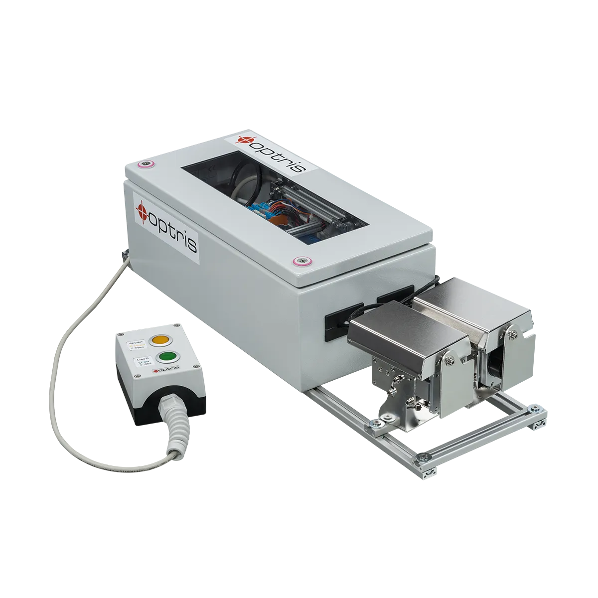
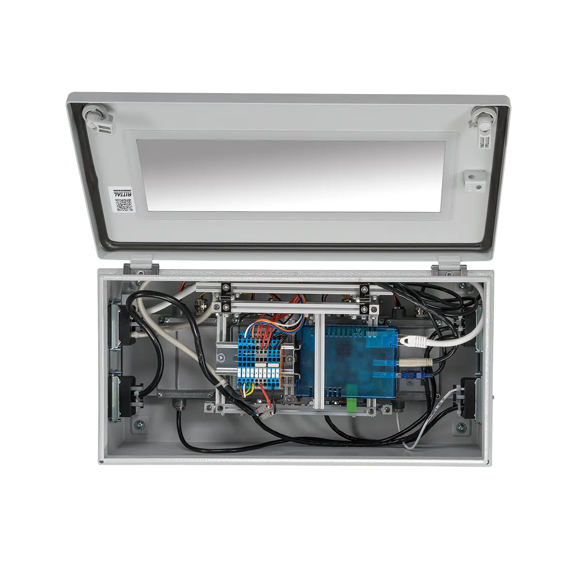
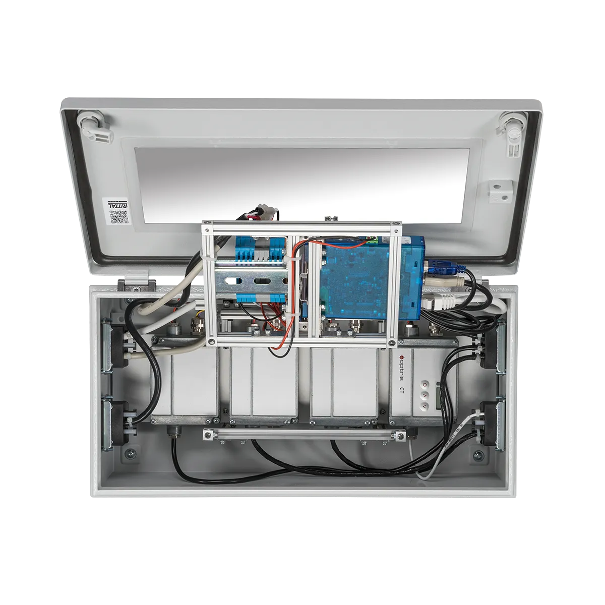
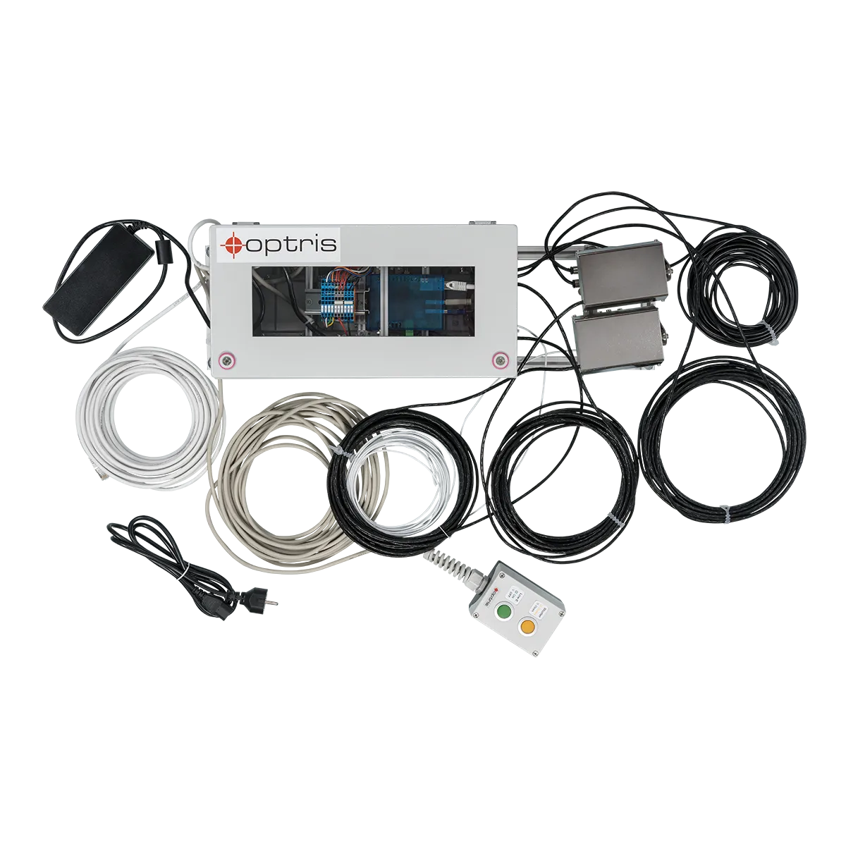
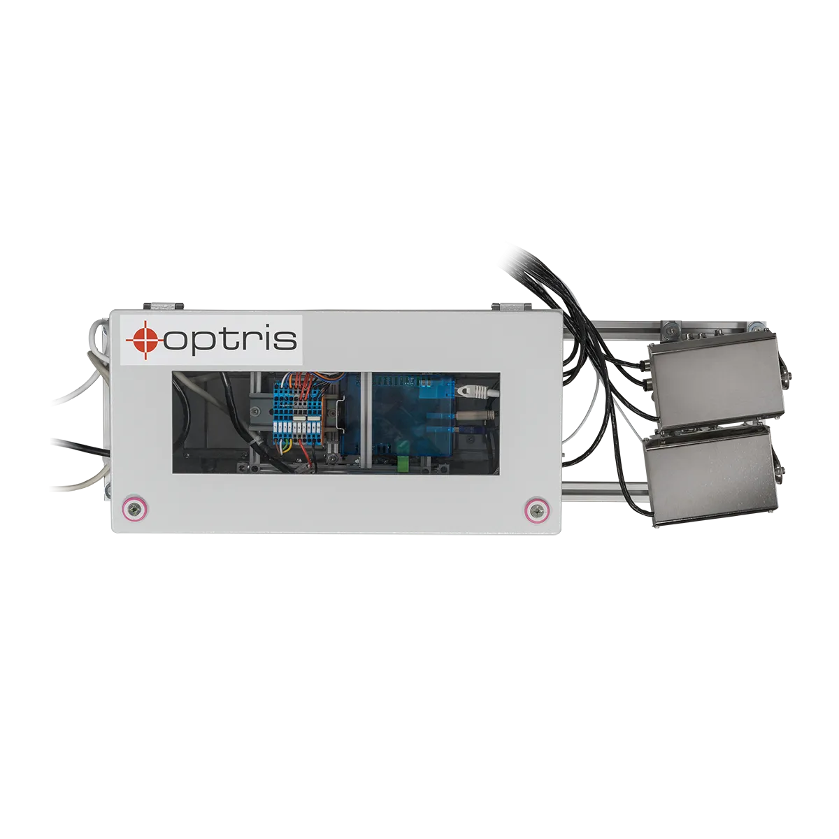
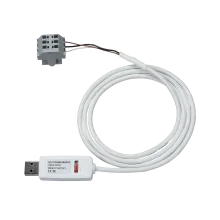
The Top-Down GIS is delivered as a pre-assembled system for easy installation on glass tempering furnaces. This turnkey solution simplifies the implementation process, allowing manufacturers to quickly integrate the system into their existing production lines. The system’s design ensures minimal disruption during installation while providing immediate benefits in terms of temperature measurement accuracy and process control. It consists of several pre-wired components ready for immediate use. The infrared glass system is supplied with 24V and connects to a PC via an Ethernet cable. The system can be used directly with the PIX Connect analysis software and a predefined layout, enabling seamless operation and efficient data analysis from the moment it is installed.
Specification
| MODEL | TDGIS 640 G7 33°x25° | TDGIS 640 G7 60°x45° | TDGIS 640 G7 90°x64° |
| DETECTOR | |||
| Optical resolution | Full resolution: 640×480 pixels Linescan: 640×120 pixels |
||
| Pixel pitch | 17 µm | ||
| Detector | Uncooled bolometer | ||
| Spectral Range | 7.9 µm | ||
| Optical Filter | Integrated | ||
| Frame rate | Full resolution: 32 Hz Linescan: 125 Hz |
||
| OPTICAL | |||
| Field of View | 33°x25° | 60°x45° | 90°x64° |
| Focal length [mm] | 18.7 mm | 10.5 mm | 7.7 mm |
| F Number | 0.8 | 0.8 | 0.8 |
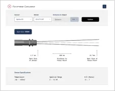
| Optical Resolution | 354:1 | 181:1 | 105:1 |
| Minimum Distance to Target | 300 mm | 200 mm | 200 mm |
| Interchangeable optics | Yes | ||
| MEASUREMENT | |||
| Object Measurement Range | 200 °C … 1500 °C 150 °C … 900 °C (Sighting range 0 °C … 250 °C) |
||
| Accuracy | ±2 °C or ±2 %, whichever is greater **6) | ||
| Thermal Sensitivity (NETD) | 80 mK | ||
| Smallest detectable Spot Size IFOV: 1 pixel | 0.3mm | 0.4mm | 0.7mm |
| Smallest measurable Spot Size MFOV | 0.9mm | 1.2mm | 2.1mm |
| Measurement Field of View (MFOV) | 3×3 pixels | ||
| Warm-up time | 10 min | ||
| Emissivity /Transmissivity/ Reflectivity | adjustable: 0.100…1.100 | ||
| INTERFACES | |||
| Interface | Ethernet over USB GigE (PoE) interface | ||
| Supported Protocols | Ethernet (max. 1000 Mbit/s) | ||
| Compatible Software | PIXConnect, ConnectSDK, EasyAPI, ExpertAPI | ||
| IMAGE PROCESSING | |||
| Configuration | via PIXConnect | ||
| Operation | computer-enabled | ||
| Capabilities | For Measurements on Glass, Measure Areas of Interest, Linescanner, EventGrabber, Merger, Alarming, Comparison Functions, Temperature-Time Diagrams, Temperature Profiles, Recording & Playing, Triggering | ||
| REFERENCE PYROMETER – DETECTOR | |||
| Detector | Thermopile | ||
| Measurement Principle | Single Color | ||
| Spectral Range | 5.0 μm | ||
| Response Time | 120 ms | ||
| Exposure Time | 120 ms | ||
| Sampling Frequency | 8 Hz | ||
| Sensing Head Exchangeable | Yes | ||
| REFERENCE PYROMETER- OPTICAL | |||
| Distance to Spot ratio (D:S) | 10:1 | ||
| Spot size (SF optics) | 7 mm | ||
| Smallest spot (CF optics / add. CF lens) | N/A | ||
| Distance | independant | ||
| REFERENCE PYROMETER – SIGHTING | |||
| Sighting | none | ||
| REFERENCE PYROMETER – MEASUREMENT | |||
| Object Measurement Range | L: 100 … 1200 °C | ||
| Accuracy | ±2 °C or ±1 % **2) | ||
| Repeatability | ±0.5 % or ±0.5 °C **1) **2) | ||
| Temperature Coefficient | ±0.05 K/ K or ±0.05 %/ K **3) | ||
| Thermal Sensitivity (NETD) | L: 100 mK | ||
| Warm-up time | none | ||
| Emissivity /Transmissivity/ Reflectivity | 0.100 – 1.100 | ||
| Slope | N/A | ||
| GENERAL | |||
| Shutter Size | 116 x 57 x 121 mm | ||
| Cabinet Size | 400 x 200 x 155 mm | ||
| Housing Material | Stainless Steel | ||
| Weight | 13 kg (complete system) | ||
| Focus | fixed | ||
| Country of Origin | Germany | ||
| ENVIRONMENTAL & CERTIFICATIONS | |||
| Operating Temperature Range | 0…50°C | ||
| Storage Temperature Range | -40…85 °C | ||
| Relative humidity | 10 – 95 %, non condensing | ||
| Protection Class | IP 65 | ||
| EMC | 2014/30/EU | ||
| Shock | IEC 60068-2-27 (25 G and 50 G) | ||
| Vibration | IEC 60068-2-6 (sinus shaped) IEC 60068-2-64 (broadband noise) |
||
| Standards | CE, UKCA, RoHS | ||
| POWER | |||
| Power Supply | 100-230 VAC / 24 VDC | ||
| Current Draw | 3A | ||
| ACCESSORY | |||
| Shutter for IR Camera | Included | ||
| Shutter for Reference Pyrometer | Included | ||
| Cabinet | Included | ||
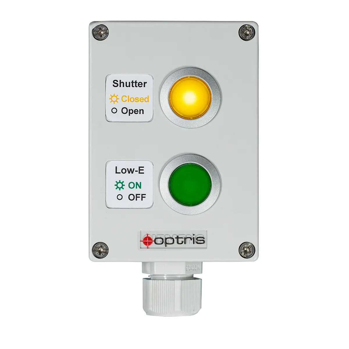
| Remote control | Included | ||
| Part number | OPTTDGIS64IO33R | OPTTDGIS64IO60R | OPTTDGIS64IO90R |
| Additional Remarks | 1) 90% energy 2) at ambient temperature 23 ± 5°C, object temperature > 0°C ; 3) for ambient temperatures <18°C and >28°C; whichever is greater 4) 90% value 5) diameter of measured area 6) Accuracy statement effective from 150 °C |
||
Areas of Application

Software
 Thermography software optris PIX Connect is included and license-free.All infrared cameras are delivered with the thermography software optris PIX Connect, developed specifically for the extensive documentation and analysis of thermal images. The Windows-based PIX Connect software enables users to tailor the infrared cameras to meet specific requirements. It analyses live and recorded temperature data and triggers alarm signals for process integration.The key to leveraging the Optris infrared camera is a correct configuration. This includes detailed device-specific configurations such as frame rate, measurement range adjustments, external communication settings, and USB/Ethernet configurations. Moreover, PIX Connect facilitates firmware updates and the download of configuration files over the Internet.
PIX Connect
Thermography software optris PIX Connect is included and license-free.All infrared cameras are delivered with the thermography software optris PIX Connect, developed specifically for the extensive documentation and analysis of thermal images. The Windows-based PIX Connect software enables users to tailor the infrared cameras to meet specific requirements. It analyses live and recorded temperature data and triggers alarm signals for process integration.The key to leveraging the Optris infrared camera is a correct configuration. This includes detailed device-specific configurations such as frame rate, measurement range adjustments, external communication settings, and USB/Ethernet configurations. Moreover, PIX Connect facilitates firmware updates and the download of configuration files over the Internet.
PIX Connect
 Optris offers several different SDKs for our Xi and PI thermal imaging cameras. Depending on the operating platform, the infrared camera, the coding language, and the hardware platform, different software interfaces can be utilized:
SDK
Optris offers several different SDKs for our Xi and PI thermal imaging cameras. Depending on the operating platform, the infrared camera, the coding language, and the hardware platform, different software interfaces can be utilized:
SDK
Downloads
FAQs
Does the system need any input?
Yes, it is recommended that the system be triggered as soon as the glass panes are measured. In this case, the shutter can stay closed when the system is not measuring, keeping the optic clean.
What is used as the reference sensor?
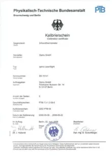
The CTlaser G5 with 5.0 µm wavelength sensitivity is used underneath the pane.
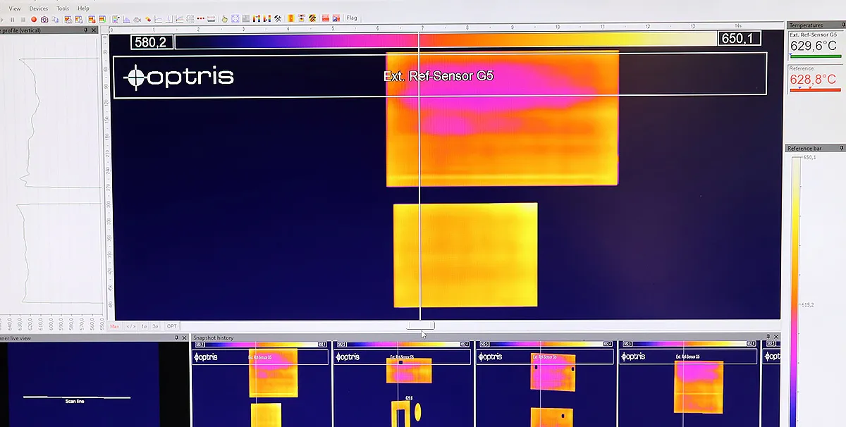
What is the system doing when a line scan is triggered?
The glass system gets the signal from the furnace; the signal opens the two shutters, and the actual process starts. The software starts the line scanning and builds the image line by line. Ultimately, a complete product image is created and automatically saved as a snapshot. Since each pixel is saved as a temperature value, an exact analysis can be performed afterward. In addition to maintaining the correct temperature, the software displays the temperature distribution as a profile. Here, it can be seen exactly how good the temperature distribution is on the glass, and inhomogeneities can be easily detected.
What kind of maintenance should be carried out?
Although the infrared cameras are protected by the shutter, when the system is not in use, the system requires a maintenance check at regular intervals. Here, it should be checked whether the camera’s optics are clean and correctly focused and whether the shutter systems still function properly. This includes a complete opening and closing of the shutters. These points must be observed, as they directly influence the temperature measurement. Never use cleaning compounds containing solvents (neither for the lens nor the housing). The lens surface can be cleaned with a soft, humid tissue (moistened with water) or a lens cleaner.
Does the temperature reading depend on the measurement angle?
Angle dependence is another important factor to consider when measuring temperature. On the uncoated side, the values are constant up to an angle of 45°. On the coated side (low-E), the 60° optics is preferred since the influence of the emissivity change is negligible here.
Why should I measure glass with a G7 infrared camera?
Accurate temperature measurement relies significantly on the emissivity of glass, a crucial determinant affected by multiple factors and tailored to specific applications. The narrowband G7 spectral range, peaking at 7.9 µm, aligns with the highest emissivity of glass, facilitating remote temperature measurement by minimizing issues related to reflectivity and transmissivity. Additionally, within this wavelength range, the angle dependency of glass surface emissivity is reduced, enabling temperature measurement irrespective of reflection, even at inclined viewing angles.
How do I align the camera?
The G7 infrared camera offers a sighting mode in which an infrared image is shown, but no temperature values are measured.
Scope of Supply
- PI 640i imager with 60° or 90° FOV
- Industrial Process Interface
- CT G5L reference sensor with USB interface and calibration certificate
- DCLP Shutter system with mounting brackets for imager and reference sensor
- USB Server Gigabit
- Control cabinet
- Cable set
- Remote control box
- Software package
- 100-230 V AC/ 24 V DC power supply for initial start-up


Talk to us about your IR Temperature Measurement Requirements
Our Infrared Temperature Measurement experts can help you find the right Optris product for your application.
